ON THIS PAGE:
The Logic process independently evaluates up to four different inputs, each with its own limits and offsets. The different states (state 1 up to state 8), are determined based on the application of various logic rules that use one or more of the input evaluation outcomes as their operands. For example, a State 1 event is raised if the State 1 logic state was defined as:
Input 1 data is below the Input 1 minimum offset
AND Input 2 data is above the Input 2 maximum offset
and if both of these conditions occur simultaneously (at the same sample interval)
Also, when used as part of a Logic state expression, the inputs for the Logic process can each have a duration specified, whereby an outcome has to be above the maximum offset for the full specified duration to be considered “above the maximum offset”, or, likewise, it should be below the minimum offset for the full specified duration to be considered “below the minimum offset”.
Logic Process allows multiple logical combinations and inputs to be used, to determine the different states. This process is particularly useful when you need to measure several inputs simultaneously, and when combinations of conditions should raise various states.
State Transition Rules
Unlike many of the other Sentinel processes, the Logic process does not have a state transition logic path. Transition from one state to another depends entirely on the current evaluation of data, and is unaffected by the current state.
However, the different states follow a rule of precedence, thus allowing for the escalation of actions based on severity, via the Sentinel framework. Different actions can be assigned to different state outcomes.
Logic states are given priority in the order they are defined. So, State 1 is evaluated first. If the logic fails, then State 2 is evaluated, and so on. Thus it makes sense to put the highest severity items in the highest positions (State 1 and State 2), and reserve the lower severities for the lowest positions.
The following table lists the order of precedence for the Logic process logic states.
| Logic State | Under these conditions |
| State 1 | This has the highest priority. |
| State 2 | This has the second highest priority. |
| State 3 | This has the third highest priority. |
| … | … |
| State N -1 | This has the second lowest priority. |
| State N | This has the lowest priority. |
Test Outcomes
A number of outcomes are possible when the Logic process is executed:
| Default State | The default state is reached when none of the logic states evaluate to True, and when the monitor is not in a suppressed state. |
| State 1 | Boolean logic is applied to the operators and operands defined for State 1. If the logic evaluates to True, and if the monitor is not already in State 1, State 1 is reached and a State 1 event is raised. |
| State 2 | Boolean logic is applied to the operators and operands defined for State 2. If the logic evaluates to True, and if the monitor is not already in State 2, State 2 is reached and a State 2 event is raised. |
| State 3 | Boolean logic is applied to the operators and operands defined for State 3. If the logic evaluates to True, and if the monitor is not already in State 3, State 3 is reached and a State 3 event is raised. |
| State 4 | Boolean logic is applied to the operators and operands defined for State 4. If the logic evaluates to True, and if the monitor is not already in State 4, State 4 is reached and a State 4 event is raised. |
| State 5 | Boolean logic is applied to the operators and operands defined for State 5. If the logic evaluates to True, and if the monitor is not already in State 5, State 5 is reached and a State 5 event is raised. |
| State 6 | Boolean logic is applied to the operators and operands defined for State 6. If the logic evaluates to True, and if the monitor is not already in State 6, State 6 is reached and a State 6 event is raised. |
| State 7 | Boolean logic is applied to the operators and operands defined for State 7. If the logic evaluates to True, and if the monitor is not already in State 7, State 7 is reached and a State 7 event is raised. |
| State 8 | Boolean logic is applied to the operators and operands defined for State 8. If the logic evaluates to True, and if the monitor is not already in State 8, State 8 is reached and a State 8 event is raised. |
| Suppressed State | The monitor has been suppressed. For example, if the precondition has not been met. |
Conditional Logic
The Logic process provides the following conditional logic.
Note: All of the example graphs in the following sections show tests that have used the Last Known Value sample method.
Evaluating the Different States
Up to eight different states (State 1 through to State 8) can be set up for evaluation. Any state can only be raised if evaluations for preceding states have evaluated to False. For example, State 6 can only be raised if it evaluates to True and State 1, State 2, State 3, State 4 and State 5 all evaluate to False. Likewise, State 3 can only be raised if it evaluates to True and State 1 and State 2 both evaluate to False.
Mode Settings
The mode settings apply to all of the defined Inputs.
Offset Mode
The offset mode is set to be fixed or percentage, and applies to all of the defined limits. When offset mode is fixed value, it is added to (or subtracted from, in the case of a negative offset) the limit value. If an offset is a percentage, then it is multiplied against the limit value and the resulting product is added or subtracted to the limit value.
Suppress Minimums
If the Suppress all minimums if any input is within limits of offsets check box is selected, all inputs are evaluated as a group, in the following way.
If any of the inputs is within its limits, then none of the other inputs can be evaluated as “below minimums”, even if they have had a minimum offset defined. For example, if Input 2 data is within its offset limits, then Input 1, Input 3 and Input 4 cannot be evaluated as “below minimum”.
Input 1 |
However, because Input 2 is within the offset limits at this time, and the Suppress all minimums if any input is within limits of offsets check box is selected, Input 1 is not “below minimum”, but “within limits”. |
Input 2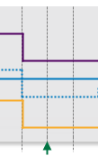 |
Because of this, there can be no “below minimum” evaluations for any of the other limits at 11:00am. |
Input 3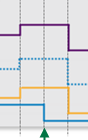 |
However, because Input 2 is within the offset limits at this time, and the Suppress all minimums if any input is within limits of offsets check box is selected, Input 3 is not “below minimum”, but “within limits”. |
Input 4 |
Input 4 evaluates as “above maximum” at 11:00am. |
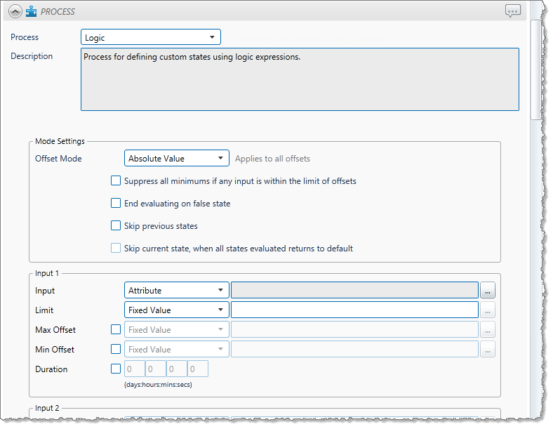
Defining Inputs
At least one, and up to four different inputs can be set up in the Logic process. Of those inputs that are set up, various evaluation outcomes can be used as operands in the logic applied to the different states. Each input (Input 1, Input 2, Input 3 and Input 4) has its own settings:
- Input: The data that is evaluated.
- Limit: The base value from which the offsets are calculated.
- Max Offset: If this is selected, then it is the value by which the maximum offset is calculated; this value is applied to the limit, either as a percentage or as an absolute value (depending on the selected offset mode).
- Min Offset: If this is selected, then it is the value by which the minimum offset is calculated; this value is applied to the limit, either as a percentage or as an absolute value (depending on the selected offset mode).
- Duration: If a duration is defined, this affects the evaluation of an input. An input will only be evaluated as “below minimum” when it remains below the minimum offset for longer than that input’s defined duration. Likewise, an input will only be evaluated as “above maximum” when it remains above the maximum offset for longer than that input’s defined duration.
Example: Evaluating an Input with Min Offset Duration
The following example demonstrates how an input is only evaluated as “below minimum” after a certain duration. In this example, duration is defined as 1 hour and 55 minutes.
09:00am 10:00am 11:00am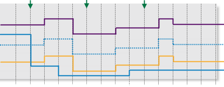 |
|
|
Determining States
The Logic process requires that at least one state (State 1) is defined. Up to eight different states can be defined. Each state is made up of a combination of outcomes of the various inputs.
For example, State 1 can be defined as: 1 Max AND 3 Min OR 2 Max AND 4 Min
In order for State 1 to be raised, the following evaluations must occur simultaneously: Input 1 evaluates to “above maximum” AND Input 3 evaluates to “below minimum” OR Input 2 evaluates to “above maximum” AND Input 4 evaluates to “below minimum”.
How the Logic Process Evaluates Conditions
Each state has up to four operands, with up to three logical operators. The Logic process uses Boolean logic to evaluate conditions.
In Boolean Logic, the rules to be aware of are:
- “And” takes precedence over “or”
- “True and True” evaluates to True
- “True and False” evaluates to False
- “False and False” evaluates to False
- “True or False” evaluates to True
- “False or False” evaluates to False
- “True or True” evaluates to True
For Sentinel, group pairs according to the precedence rules, and then from left to right, to better understand how the logical evaluation is performed:
1 Min and 2 Max or 3 Min and 4 Min groups to:
(1 Min and 2 Max) or (3 Min and 4 Min), and is evaluated as:
(True) or (False), which is further evaluated to the final outcome:
True
The following table demonstrates how various states have been set up, and are then evaluated. The highest state (closest to State 1) takes precedence over other states.
| Evaluate: | Expression evaluates to: | Evaluates to | Raises a State | ||||||
| Operand & (operator) | 1 | (1) | 2 | (2) | 3 | (3) | 4 | ||
| State 1 | True | AND | True | AND | False | OR | False | False | No state raised (False outcome) |
| State 2 | True | AND | False | OR | True | AND | True | True | State 2 is raised |
| State 3 | True | AND | True | AND | True | AND | True | True | State 2 takes precedence |
| State 4 | True | OR | False | AND | True | - | - | - | State 2 takes precedence |
| State 5 | - | - | - | - | - | - | - | - | No State Defined |
| State 6 | - | - | - | - | - | - | - | - | No State Defined |
| State 7 | - | - | - | - | - | - | - | - | No State Defined |
| State 8 | - | - | - | - | - | - | - | - | No State Defined |
In the example, State 1 is evaluated as follows:
| Operand 1 | Operator 1 | Operand 2 | Operator 2 | Operand 3 | Operator 3 | Operand 4 | Final Outcome |
| 1 Max | AND | 3 Min | AND | 2 Max | OR | 4 Min | |
| True | AND | True | AND | False | OR | False | |
| True | AND | False | OR | False | |||
| False | OR | False | |||||
| False |
State 2 is evaluated as follows:
| Operand 1 | Operator 1 | Operand 2 | Operator 2 | Operand 3 | Operator 3 | Operand 4 | Final Outcome |
| 1 Max | AND | 4 Min | OR | 2 Min | AND | 3 Min | |
| True | AND | False | OR | True | AND | True | |
| False | OR | True | |||||
| True |
State 3 is evaluated as follows:
| Operand 1 | Operator 1 | Operand 2 | Operator 2 | Operand 3 | Operator 3 | Operand 4 | Final Outcome |
| 1 Max | AND | 3 Min | AND | 2 Min | AND | 4 Max | |
| True | AND | True | AND | True | AND | True | |
| True | AND | True | |||||
| True |
and so on.
Definition of Operands in the Logic Process
The following operands are available to the Logic Process. Note that for any of the limits, “within limits” means that a limit has not been exceeded. In these definitions, N could be 1, 2, 3 or 4 and is referring to the different inputs: Input 1, Input 2, Input 3, Input 4.
| N Min | If the input value for N is currently lower than the minimum offset for N, and has been, continuously, for longer than the defined duration (if any duration has been defined for Limit N) , or if it is currently lower than the minimum offset for N (if no duration has been defined) then N Min evaluates to True. Otherwise, it evaluates to False.
Example: 1 Min, refers to the Minimum Offset for Input 1. |
| N Max | If the input value for N is currently higher than the maximum offset for N, and has been, continuously, for longer than the defined duration (if any duration has been defined for Limit N) , or if it is currently higher than the maximum offset for N (if no duration has been defined) then N Max evaluates to True. Otherwise, it evaluates to False.
Example: 2 Max, refers to the Maximum Offset for Input 2. |
| N Out | If the input value for N is currently lower than the minimum offset for N, and has been, continuously for longer than the defined duration (if any duration has been defined for Limit N) , or if it is currently lower than the minimum offset for N (if no duration has been defined) then N Min evaluates to True. Otherwise, it evaluates to False. Example: 1 Min, refers to the Minimum Offset for Input 1. Or, if the input value for N is currently higher than the maximum offset for N, and has been, continuously, for longer than the defined duration (if any duration has been defined for Limit N) , or if it is currently higher than the maximum offset for N (if no duration has been defined) then N Max evaluates to True. Otherwise, it evaluates to False. Example: 2 Out, refers to the Maximum Offset and the Minimum Offset for Input 2. |
| N In | If the input value for N is less than or equal to the maximum offset value, and also greater than or equal to the minimum offset value (regardless of duration), then N In evaluates to True. Otherwise, it evaluates to False. Example: 2 In, refers to the Maximum Offset and the Minimum Offset for Input 2. N In, with Suppress all minimums… |
Example: Determining States
The following illustration demonstrates how at 11:00am State 1 is raised when Input 1 evaluates to “above maximum” while Input 3 evaluates to “below minimum”.
| Input evaluation | Logical evaluation | |||||||
Input 1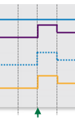 |
For Input 1, data is “above maximum”. |
Input 3 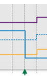 |
For Input 3, data is “below minimum”. |
1 Max and 3 Min | ||||
| 1 Max true |
and and |
3 Min true |
true |
|||||
Input 2 |
For Input 2, data is “within limits”, that is it’s not “above maximum”. |
Input 4 |
For Input 4, data is “below minimum”. |
2 Max and 4 Min | ||||
| 2 Max false |
and and |
4 Min true |
false |
|||||
1 Max AND 3 Min OR 2 Max AND 4 Min evaluates to TRUE OR FALSE.
TRUE OR FALSE evaluates to TRUE. Thus a State 1 event is raised, and State 1 is reached.
Adding a Logic Process
The Sentinel Logic Process uses Boolean logic to use the outcome of up to four different inputs to establish various states.
Setting Process Values and Limits
Part of setting up the Logic process involves selecting values, such as the different inputs, the different limits, and the minimum and maximum offsets. Values can either be fixed, or they can be variable data taken from tags.
The following values are available. Select a value type from the drop-down list, then type in or select a value.
- Fixed Value: If you choose this, type in a fixed numerical value. Note: This is not an option for Input 1.
- Attribute: This option is only available if the test’s Source Type is Entity or Hierarchy. Click the ellipsis
 button to select an attribute of the source entities.
 - Source Tag: This option is only available if the Source Type is Tag.
- Calculation: Click the ellipsis
 button to open the Edit Calculation window.
- If the Source Type is Entity or Hierarchy: Type a calculation, prefixed by ‘this’ as the Source Entity token, for example: {this:THP} + 34.
- If the Source Type is Tag: Type a calculation, prefixed by ‘this’ as the Source Tag token, for example: {this} * 2.
- Tag: Click the ellipsis
 button to select a tag.
 - Entity Attribute: Click the ellipsis
 button to select an entity. From here, select an attribute, or attribute value, for the selected entity.
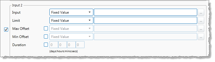
Adding the Process
As with all Sentinel processes, the Logic Process is defined within a Sentinel Test page. In the Sentinel Test page:
1. Expand the Process ![]() panel.
panel.
2. Select Logic from the Process drop-down list.
The screen now shows the details for the Logic process.
Mode Settings
The mode settings apply to all of the offsets defined in the process. The following options are available:
- Offset Mode: Percentage or Absolute Value. The offset mode determines how the max and min offsets for the various inputs are calculated from their defined limits.
- Suppress all minimums if any input is within the limit of offsets: Select the check box if you want to suppress all minimums, when any input is within the offset limits.
- End evaluating on false state: Select this check box to stop the process from continuing, after evaluating a state as false.
- Skip previous states: Select this check box to prevent the process from evaluating previous states and start from the current active state. If at State N, the process will skip evaluation of States 1 to N-1 on next run.
- Skip current state, when all states evaluated returns to default: This check box is only available if Skip previous states has been selected. Select this check box to stop the process from evaluating the current state and previous states. If at State N, the process skips evaluation of State 1 to N and starts at State N+1. Upon reaching the last State, the process will return to a default state.
Inputs
At least one and up to four different Inputs need to be specified for the Logic process.
Note: During processing, the inputs are evaluated in order of precedence (Input 1 having the highest precedent).
Input 1 (Required)
3. From the Input drop-down list, select one of the following and then select a corresponding value:
- Attribute (only available if the Source Type is Entity or Hierarchy)
- Source Tag (only available if the Source Type is Tag)
- Calculation
- Tag
- Entity Attribute
4. From the Limit drop-down list, select one of the following and then type in or select a corresponding value:
- Fixed Value
- Attribute (only available if the Source Type is Entity or Hierarchy)
- Source Tag (only available if the Source Type is Tag)
- Calculation
- Tag
- Entity Attribute
5. Optionally define a Max Offset.
Note: You must select either a Max Offset or a Min Offset, or both.
- Select the Max Offset check box.
- From the Max Offset drop-down list, select one of the following and then type in or select a corresponding value:
- Fixed Value
- Attribute (only available if the Source Type is Entity or Hierarchy)
- Source Tag (only available if the Source Type is Tag)
- Calculation
- Tag
- Entity Attribute
6. Optionally define a Min Offset.
- Select the Min Offset check box.
- From the Min Offset drop-down list, select one of the following and then type in or select a corresponding value:
- Fixed Value
- Attribute (only available if the Source Type is Entity or Hierarchy)
- Source Tag (only available if the Source Type is Tag)
- Calculation
- Tag
- Entity Attribute
7. Optionally define a duration.
- Select the Duration check box.
- Type integer values in the days, hours, mins (minutes), and secs (seconds) Duration Limit boxes to define a duration period. The default value is zero.
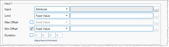
Inputs 2, 3 and 4 (Optional)
8. Select the check box to the left of the relevant Input panel (e.g. Input 2).
9. From the Input drop-down list, select one of the following and then select a corresponding value:
- Fixed Value
- Attribute (only available if the Source Type is Entity or Hierarchy)
- Source Tag (only available if the Source Type is Tag)
- Calculation
- Tag
- Entity Attribute
10. Capture the Limit, Max Offset, Min Offset and optional Duration for Inputs 2-4, following the instructions for defining Input 1.
Logic State Settings
At least one logic state (State 1) and up to eight logic states must be selected for the Logic Process.
For each logic state that you want to set up for the process, do the following:
11. Select the check box to the right of the logic state name.
12. Select the operands and operators to build up a logical expression for the state.
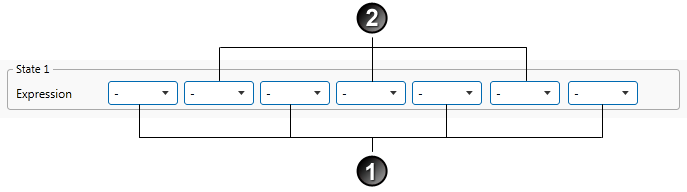
13. Select the first operand from the first drop-down list for State 1.
The operands all relate to the Min Offsets and Max Offsets of the various Inputs. All possibilities are listed in the drop-down; however, you may only select valid options (that is, options that are defined in the Inputs section). So, for example, you should not select Min 4 if you have not defined Input 4 as one of your inputs, or if you have not defined a Min Offset for Input 4.
The operand drop-down list comprises of the following:
| - | This equates to no selection, and is the default. |
| 1 Min | If the data for Input 1 is lower than the Min Offset for Input 1, for the defined duration (if applicable), 1 Min evaluates to True, otherwise False. |
| 1 Max | If the data for Input 1 is higher than the Max Offset for Input 1, for the defined duration (if applicable), 1 Max evaluates to True, otherwise False. |
| 1 Out | If the data for Input 1 is either higher than the Max Offset for Input 1, or lower than the Min Offset for Input 1, for the defined duration (if applicable), 1 Out evaluates to True, otherwise False. |
| 1 In (“Within Limits”) | If the data for Input 1 is between the Max Offset for Input 1, and the Min Offset for Input 1, for the defined duration (if applicable), 1 In evaluates to True, otherwise False. If the Suppress all minimums if any input is within limits of offsets check box is selected, and any of the other inputs is “within limits”, then if data for Input 1 is below the Max Offset for Input 1, 1 In evaluates to True, otherwise False. |
| 2 Min | If the data for Input 2 is lower than the Min Offset for Input 2,for the defined duration (if applicable), 2 Min evaluates to True, otherwise False. |
| 2 Max | If the data for Input 2 is higher than the Max Offset for Input 2, for the defined duration (if applicable), 2 Max evaluates to True, otherwise False. |
| 2 Out | If the data for Input 2 is either higher than the Max Offset for Input 2, or lower than the Min Offset for Input 2, for the defined duration (if applicable), 2 Out evaluates to True, otherwise False. |
| 2 In (“Within Limits”) | If the data for Input 2 is between the Max Offset for Input 2, and the Min Offset for Input 2, for the defined duration (if applicable), 2 In evaluates to True, otherwise False. If the Suppress all minimums if any input is within limits of offsets check box is selected, and any of the other inputs is “within limits”, then if data for Input 2 is below the Max Offset for Input 2, 2 In evaluates to True, otherwise False. |
| 3 Min | If the data for Input 3 is lower than the Min Offset for Input 3, for the defined duration (if applicable), 3 Min evaluates to True, otherwise False. |
| 3 Max | If the data for Input 3 is higher than the Max Offset for Input 3, for the defined duration (if applicable), 3 Max evaluates to True, otherwise False. |
| 3 Out | If the data for Input 3 is either higher than the Max Offset for Input 3, or lower than the Min Offset for Input 3, for the defined duration (if applicable), 3 Out evaluates to True, otherwise False. |
| 3 In (“Within Limits”) | If the data for Input 3 is between the Max Offset for Input 3, and the Min Offset for Input 3, for the defined duration (if applicable), 3 In evaluates to True, otherwise False. If the Suppress all minimums if any input is within limits of offsets check box is selected, and any of the other inputs is “within limits”, then if data for Input 3 is below the Max Offset for Input 3, 3 In evaluates to True, otherwise False |
| 4 Min | If the data for Input 4 is lower than the Min Offset for Input 4 , for the defined duration (if applicable), 4 Min evaluates to True, otherwise False. |
| 4 Max | If the data for Input 4 is higher than the Max Offset for Input 4, for the defined duration (if applicable), 4 Max evaluates to True, otherwise False. |
| 4 Out | If the data for Input 4 is either higher than the Max Offset for Input 4, or lower than the Min Offset for Input 4, for the defined duration (if applicable), 4 Out evaluates to True, otherwise False. |
| 4 In (“Within Limits”) | If the data for Input 4 is between the Max Offset for Input 4, and the Min Offset for Input 4, for the defined duration (if applicable), 4 In evaluates to True, otherwise False. If the Suppress all minimums if any input is within limits of offsets check box is selected, and any of the other inputs is “within limits”, then if data for Input 4 is below the Max Offset for Input 4, 4 In evaluates to True, otherwise False |
14. Select the first operator from the next drop-down list for State 1.
This is used for the logical evaluation, and can be any of the following:
-, And, Or.
15. Select the remaining operands and operators that you want to use for the expression.
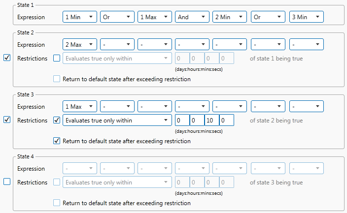
The final expression will look similar to this:

16. Continue adding logical expressions for up to 7 additional states, until you have all the states that you want for this process. For each additional state:
- Select the check box next to the state.
- Specify the Expression to evaluate, as per step 2.
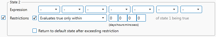
- If required, apply a Restriction by selecting the check box below the expression.
Enabling a restriction allows you to restrict the time that the state can be evaluated as true. The options in the drop-down list are:
Evaluates true only within: This option evaluates the state as true only within the specified time period (DD:HH:MM:SS) of the previous state. This requires the process to only evaluate the state as true within the time restriction. If at State N with time restriction X, then any time after X of State N-1 being evaluated as true will indefinitely return false until the next time State N-1 is raised after departing State N-1.
Evaluates true after: This option evaluates the state as true only after the specified time period (DD:HH:MM:SS) of the previous states. This requires the process to only evaluate the state as true after the time restriction. If at State N with time restriction X, then any time before X of State N-1 being evaluating true will return false until the time restriction has been met.
17. If you have applied the above restriction, you also have the option of selecting Return to default state after exceeding restriction.
When selected, the process returns to the default state when restrictions have been exceeded, as follows:
- When Evaluates true only within is being used, and any time after the time restriction where the state has yet to evaluate to true.
- When Evaluates true only after is being used, and if the state evaluates true prior to the time restriction.
The logic states may now look something like this:
Adding Comments
18. Click the comment ![]() button at the top right of the panel.
button at the top right of the panel.
Configuring States
For the Logic process, you can configure the following states, each with an optional state override and comments:
- Default
- State 1
- State 2
- State 3
- State 4
- State 5
- State 6
- State 7
- State 8
- Suppressed
You cannot change the severity of the Default state; however, you can add a state override and comments.
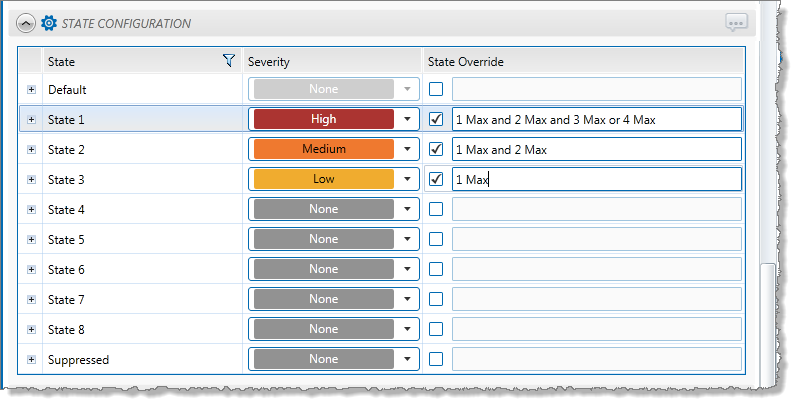
Note: Only configure states where you have set a limit.