ON THIS PAGE:
The Logic components evaluate an input against some simple logic.
Digital State
The Digital State component supplies the logic for detecting a simple digital state.
It allows you to evaluate a text data point against specified values, and evaluate the result as either true or false.

Properties
Case sensitive comparison?
This check box, if selected, allows strings to be compared on the basis of upper and lower-case letters. For example, String will be considered as being different to string.
Inputs
Flow ![]()
The component that causes the digital state logic to execute should be connected to the flow pin for this component.
Text ![]()
This input is mandatory and is the input data point.This input is required. Not connecting this pin will produce an error.
T ![]()
The state text that is matched to produce a value of true. This input is required. Not connecting this pin will produce an error.
F ![]()
The state text that is matched to produce a value of false. This input is required. Not connecting this pin will produce an error.
Outputs
Boolean ![]()
Following evaluation, the true or false value is output from this pin. Not connecting this pin will produce a warning.
err ![]()
If in does not match either state T or F, the process follows this path.
Example
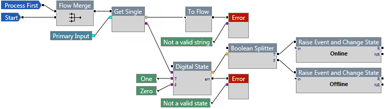
In the following example, two events may be raised.
If the input is a string, the Digital State component is run. The string is then evaluated to see if it is equal to One or Zero.
The state of the entity changes to Online when the input is evaluated as true (input is "One").
The state of the entity changes to Offline when the input is evaluated as false (input is "Zero").
Drift Detector
The Drift Detector component supplies the logic for detecting the deviation between process data inputs and reference inputs. The reference inputs can be a fixed value, or it can be a dynamic value from another data stream.

Properties
Limit Offset Mode
Absolute or Percentage. Indicate whether to specify actual values for the upper and lower limits, or whether to specify the upper and lower limits as a percentage offset from the target value.
Inputs
The input pins are mandatory. If they are not connected, the component will not be able to run.
Flow ![]()
The component that causes the drift detection logic to execute should be connected to the flow pin for this component.
in ![]()
This input is mandatory and is the input data stream. This input is required. Not connecting this pin will produce an error.
target ![]()
The target value. This input is required. Not connecting this pin will produce an error.
upper ![]()
The upper limit value or percentage offset from the target value.
lower ![]()
The lower limit value or percentage offset from the target value.
Outputs
The output pins are optional. Not connecting an output pin will produce a warning.
above ![]()
If the input value is above the upper limit, the process follows this path.
normal ![]()
If the input value is between the upper limit and lower limit, the process follows this path.
below ![]()
If the input value is below the lower limit, the process follows this path.
Example
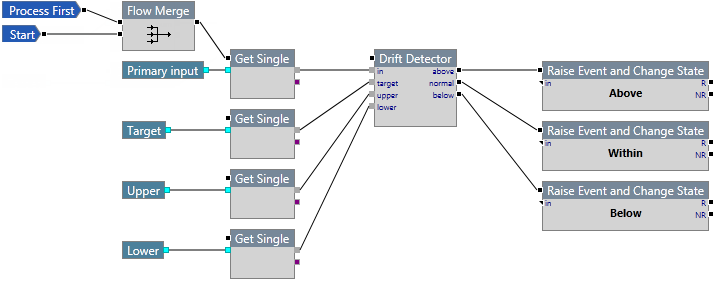
In the following example, three events may be raised.
Data is fetched from four sources. The value is then evaluated against the target, upper limit, and lower limit.
The state of the entity changes to Above when the input is evaluated as being above the upper limit.
The state of the entity changes to Below when the input is evaluated as being below the lower limit.
The state of the entity changes to Within when the input is evaluated as being between the upper limit and lower limit.
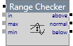
Range Checker
The Range Checker component supplies the logic for detecting the deviation between process data inputs and reference inputs. The reference inputs can be a fixed value, or it can be a dynamic value from another data stream.
Properties
This component has no additional properties.
Inputs
The input pins are mandatory. If they are not connected, the component will not be able to run.
Flow ![]()
The component that causes the range checker logic to execute should be connected to the flow pin for this component.
in ![]()
This input is mandatory and is the input data stream. Not supplying this input pin will produce an error and the process will not run.
max ![]()
The maximum value the input should have.
min ![]()
The minimum value the input should have.
Outputs
The output pins are optional. Not connecting an output pin will produce a warning.
above ![]()
If the input value is greater than the maximum value, the process follows this path.
normal ![]()
If the input value is between the maximum and minimum values, the process follows this path.
below ![]()
If the input value is less than the minimum value, the process follows this path.
Example
In the following example, three events may be raised.
Data is fetched from three sources. The value is then evaluated against the maximum and minimum values.
The state of the entity changes to Above when the input is evaluated as being above the maximum value.
The state of the entity changes to Below when the input is evaluated as being below the minimum value.
The state of the entity changes to Within when the input is evaluated as being between the maximum and minimum values.
