ON THIS PAGE:
The Flow components are used to direct the process flow to follow a certain path, depending on the output.
Boolean Splitter
The Boolean Splitter component accepts a Boolean input and directs it to a specific flow, depending on whether the input is true or false.
Properties
This component has no additional properties.
Inputs
Flow ![]()
The component that acts as a trigger for this component should be connected to this pin. This pin is optional.
Boolean ![]()
A Boolean input. This input is required. Not connecting this pin will produce an error. Components that can be connected to this include:
- Any of the Boolean components (except Binary Combiner and Boolean Selector)
- Contains
- Ends With
- Starts With
Outputs
T ![]()
If the input is true, the process follows this path. The input value of true is not passed along the process flow. Not connecting this pin will produce a warning.
F ![]()
If the input is false, the process follows this path. The input value of false is not passed along the process flow. Not connecting this pin will produce a warning.
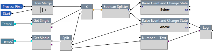
Example
In the following example, a data point is evaluated to see if it is less than or equal to another data point. If it is, the Boolean Splitter directs the process flow to the true output pin, raises an event, and changes the state of the entity to Below; otherwise, the process follows the false output pin, raises an event, changes the state of the entity to Above, and then logs the value.
End
The End component stops the process as a success. It is typically used in conjunction with a Flow Sequence component to stop the process if a condition is met.
![]()
Properties
This component has no additional properties.
Inputs
Flow ![]()
The component that acts as a trigger for this component should be connected to this pin.
Outputs
This component has no output pins.
Example
In the following example, the End component terminates the process if the value of Temp 1 is greater than the value of Temp 2 plus 25. In this case, an event is raised and the state of the entity changes to Primary, then the process ends.
If Temp 1 is not greater than Temp 2+25, the process returns to the Flow Sequence and checks to see if Temp 1 is greater than Temp 2 + 10. In this case, an event is raised and the state of the entity changes to Secondary, then the process ends.
If Temp 1 is not greater than Temp 2+10, an event is raised and the state of the entity changes to Default.

Error
The Error component generates an error in the log and terminates the process flow.
![]()
Properties
This component has no additional properties.
Inputs
Flow ![]()
The component that acts as a trigger for this component should be connected to this pin.
Text ![]()
The text for the error message, which will be displayed in the log messages. While running in a monitor, this message is shown in the monitor status page. The monitor will stop and re-run.
Outputs
This component has no output pins.
Example
In the following example, the process is terminated in two places due to error. The first termination point is upon getting the primary input. If the input is a number, it is sent to error with an error message of "Not a valid string". The second termination point is if the digital state cannot resolve to either true or false; in this case an error is produced with the message, "Not a valid state".
Note that when using a .csv file to test this process, the test will stop and restart at the next row when the process encounters the error component.
Flow Merge
The Flow Merge node accepts two or more input flows in order to direct the process flow path. No data is passed through this component.

Properties
Num Inputs
The number of input pins for this component. You can specify up to 16 inputs.
Inputs
Flow ![]()
The flows that are to follow the output path should be connected to this component. All Flow Event components may also be used as inputs, as well as error output pins on other components. Other components that can be used here include:
- Raise Event
- Raise Event and Change State
- Boolean Splitter
- Selector
- Trigger
- Drift Detector
- Range Checker
- Delete Memory
Outputs
Flow ![]()
The output pin is a flow pin that directs the process flow but does not pass any data. Not connecting this pin will produce a warning.
Example
In the following example, Flow Merge is used to combine the Start and Process First flow events.
Flow Sequence
The Flow Sequence component iterates the process path over each output connection, from the first pin at the top to the last pin at the bottom.
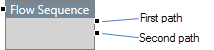
The process first follows the first path, and once that path has finished the process returns to the Flow Sequence component and commences the second path, and so on until the last path is completed, or until the iteration is stopped prematurely by an End or Error component.
Properties
Num Outputs
The number of output pins for this component. You can specify up to 16 outputs.
Inputs
Flow ![]()
The component that acts as a trigger for this component should be connected to this pin.
Outputs
Flow ![]()
The output pins are optional. They direct the process flow but do not pass any data. Missing output connections will be skipped in the process flow.
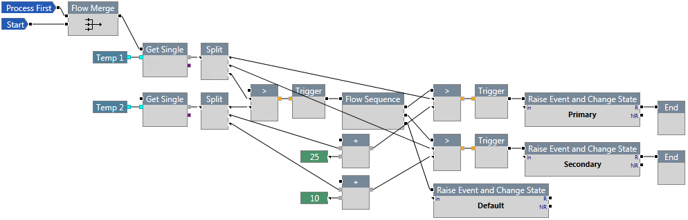
Example
In the following example, Temp 1 is checked against Temp 2. If Temp 1 is greater than Temp 2, the following things happen:
- Temp 1 is checked to see if it is greater than Temp 2 + 25. If it is, an event is raised, the state of the entity changes to Primary, and the process ends.
If not, the process returns to the next output pin of the Flow Sequence. - Temp 1 is checked to see if it is greater than Temp 2 + 10. If it is, an event is raised, the state of the entity changes to Secondary, and the process ends.
If not, the process returns to the next output pin of the Flow Sequence. - When the process reaches the final pin in the Flow Sequence, an event is raised and the state of the entity changes to Default.
Selector
The Selector component directs the process flow according to the number supplied as input.

Properties
Num Outputs
The number of output pins for this component. You can specify up to 16 outputs. The outputs are numbered sequentially, starting at 0.
Inputs
Flow ![]()
The component that acts as a trigger for this component should be connected to this pin.
Number ![]()
An integer that matches one of the numbers indicated on the output pins. A Binary Combiner or Text → Index component is typically supplied as an input to this component.
Outputs
Flow ![]()
The output pins are flow pins that direct the process flow but do not pass any data.
- If the input corresponds to an output pin that does not exist, an error is generated and the process aborts.
- If the input corresponds to an output pin that is not connected, the flow execution skips that step and attempts to recover, ending gracefully if no further processing can occur.
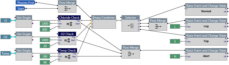
Example
In the following example, the process performs a number of calculations and places the results in a Binary Combiner. The binary combiner converts the inputs to an integer, which is passed to the Selector. Depending on the number received by the Selector, the process will raise an event and change the state of the entity to Normal, Log, or Trip.
State Machine
The State Machine component accepts a text input and compares it with the states specified in its properties. The states are configurable and are presented as output pins.
The process follows the path of the output pin that matches the input. The states in the process must match the states specified in the State Machine.

Properties
Case sensitive comparison
This check box, if selected, allows strings to be compared on the basis of upper and lower-case letters. For example, String will be considered as being different to string.
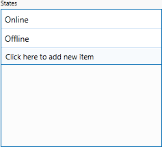
States
Allows you to specify the names of the states for the State Machine component. Click the "Click here to add new item" bar to add a new state, pressing Enter after each one. A state represents the data it is receiving and should be named accordingly.
Inputs
Flow ![]()
The component that acts as a trigger for this component should be connected to this pin.
Text ![]()
The input text string that is used for comparison against the states. Typically, the System Variable "Current State" is used as the input component. Other components that may be used here include:
- Get First
- Get Index
- Get Last
- Get Single
- Concatenate
- Join Text
- Number → Text
- To Lower Case
- To Upper Case
- Time Period → Text
- Time → Text
Outputs
Flow ![]()
The states defined in the module properties are present as output pins on the component. The process follows the path of the pin that matches the input.
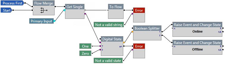
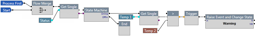
Example
In the following example, the Status is checked to see if the entity is online or offline. If the entity is online, the process retrieves the value for Temp 1 and raises an event if it is greater than Temp 2. If the entity is offline, the process ends.
To Flow
The To Flow component passes data, without processing it, to the output pin. You would use this component if you need to connect an output pin to a flow pin but it is of a different data type.

Properties
Num Inputs
The number of input pins for this component. You can specify up to 8 inputs.
Inputs
Mixed ![]()
This input accepts multiple data types.
Outputs
Flow ![]()
The output pin is a flow pin that directs the data to the connected component. Not connecting this pin will produce a warning.
Example
In the following example, the primary input is fetched. If the input is a number, the process will not work as intended so an error is produced. However, the Error component only accepts a flow pin. To invoke the Error component, a To Flow component is placed between Get Single and Error, so that an error message may be displayed.

Trigger
The Trigger component is used to initiate another component if the Boolean input is true. If the input is false, the connected component does not run. It is often used to trigger an event following a Boolean evaluation.

Properties
This component has no additional properties.
Inputs
Boolean ![]()
A Boolean input. This input is required for the component to run. Not connecting this pin will produce an error. Components that can be connected to this include:
- Any of the Boolean components (except Binary Combiner and Boolean Selector).
- Contains
- Ends With
- Starts With
Outputs
Flow ![]()
The output pin is a flow pin that directs the process flow but does not pass any data. This pin is optional and is only followed if the input is true. Not connecting this pin will produce a warning.
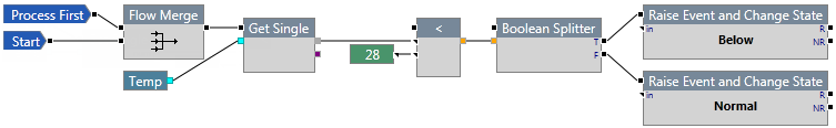
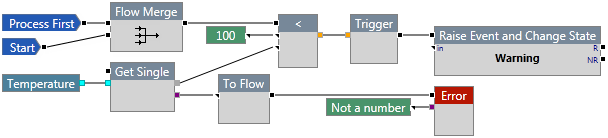
Example
In the following example, if the Temperature is greater than 100, an event is raised and the state of the entity changes to Warning. If the Temperature is 100 or less, the process does nothing.
Warning
The Warning component ends the user process execution as a warning. It can be used to raise a warning message in the Sentinel monitor status page.

Properties
This component has no additional properties.
Inputs
Flow ![]()
The component that acts as a trigger for this component should be connected to this pin.
Text ![]()
The text for the warning message, which will be displayed in the log messages. While running in a monitor, this message is shown in the monitor status page.
Outputs
This component has no output pins.